Search This Blog

Tuesday 20 November 2012

Windows 2012 Server - How do I change my product key?

You may find when you try to activate your Windows 2012 Server that activation fails and then when you try to change your product key you cannot see how to do this. Well it turns our Microsoft have removed this by default, you cannot change your product key until you activate, you cannot activate until you change your product key. Catch 22. So what do you do?

Windows Activation

media_1353410455363.png

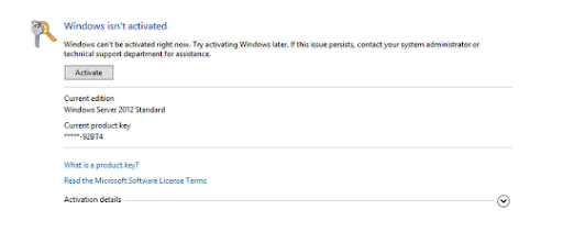
Go to the Action Center and then choose Windows Activation and you will be shown the screen above, that Windows is not activated. So we will try to activate.

Activation

media_1353410464231.png

Activation is attempted online.

Activation Failure

media_1353410471073.png

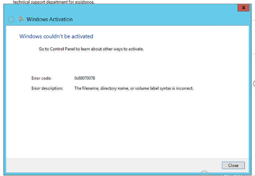
Well Windows Activation fails which is a bit disappointing, but thats OK as I didn't enter my key when I installed so I will just enter that now. Ah there does not seem to be a way to do this like there was in Windows 2008 R2. So what do I do?

The Answer

The answer is found here in this rather nice KB from Microsoft http://support.microsoft.com/kb/2750773?wa=wsignin1.0

Charm Bar

media_1353410504751.png

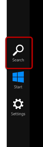
So now you need to get the Charm Bar out, this is done with Windows Key and C. Then choose the Search option.

Search

media_1353410516909.png

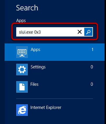
We need to search for the actual Windows Activation executable, this is called slui.exe 0x3 Don't forget the 0x3 on the end of this.

Change Product Key Time

media_1353410526820.png

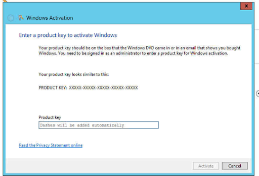
Now we can see the familiar change product key window and we can enter our correct product key.

Add Product Key

media_1353410554839.png

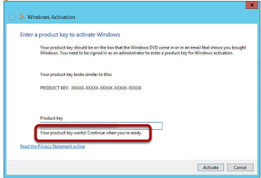
Enter your product key and it will be verifed as correct for you.

Activate

media_1353410574842.png

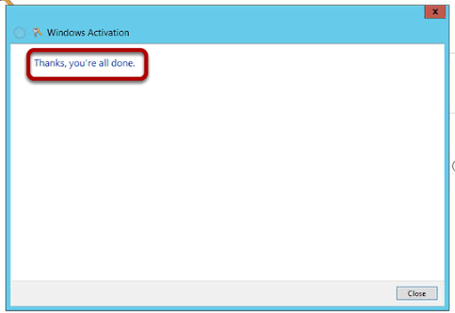
You can now perform the activation and get this cheery greeting from Redmond.

Wednesday 14 November 2012

Do you let it get to you?

Sometimes we let life get to us, be it work, home or just getting stuck in a traffic jam, life has a habit of testing us on a daily basis.  The result of this is stress, all of us suffer from it and it affects us all in different ways, what is really important is how we handle this stress.

I work in a technical based service industry, that is one of the most stressful jobs there is.  OK I am not under fire in Afghanistan and I am not an Emergency Room Doctor but never the less, the service industry is one in which everyone wants everything done yesterday.

In the past I used to think I could get everything done each day, I would work more and more hours thinking I could get the work completed but the more I did the more work came in, I never caught up.  I was spending 10 hours in the office and 4 hours a night on the laptop.  Suffice to say it did me no good.

I started to get head aches, tense muscles, feelings of being uncomfortable, physical symptoms I could feel but there was nothing wrong with me if you looked at me.  I became irritable at work and would be seen as moody, the smallest question or issue and I would feel cornered and snap at my colleagues.

I recognised this a few years ago and sought help, now I have what you can call insight and I can see when I am stressed and I try to take actions to prevent it.

One thing I have noticed now is the behavior of a stressed person at work and I try to let them know and help them by talking and asking them if they need to share a problem.  One of the main causes is that we feel we have no control, that life is controlling us.  This is a common fear and one that affects those who do not like flying for example, its not being in an airplane it is because we are not in control of it and we have to trust someone else with our life for a period of time.

Work is no different, if we feel we have no control then we will become stressed.  We will try to do it all ourselves and this just is not possible anymore, there is too much information.  We need each other.

When you feel angry or frustrated at work, take a moment and ask yourself.


  • Do you feel you have so much work to do you don;t know where to start?
  • Do you feel no one tells you what you need to know?
  • Phones ringing or people asking you questions, makes you angry quickly?
  • When you get home you just want to sleep?
These are all key indicators of stress and depression.  Do not be worried, it is normal and it happens to all of us.  Seek help, talk to friends, your partner, family, colleagues.  Just let people know and understand that life it tough and sometimes we all need help to get through.

Further Reading


Tuesday 13 November 2012

Windows 2012 - How to configure Multi Path iSCSI I/O

This is how to configure Multi Path I/O for iSCSI on Windows 2012 Server. I want to use this for our Hyper-V implementation to increase through put and redundancy.

Setup iSCSI NICs

media_1352814175635.png

In this server I have eight NICS, I have chosen to use two NICS for iSCSI and here you can see I have chosen to use one onboard Broadcom NIC and one PCI-e slot Intel NIC. Each NIC is configured with an IP address in the subnet of the storage network. In this case it is

10.12.0.40 255.255.255.0
10.12.0.41 255.255.255.0

The SAN is a HP MSA P2000 G3 iSCSI LFF and I have configured the Host NICS as

10.12.0.21 255.255.255.0
10.12.0.22 255.255.255.0
10.12.0.23 255.255.255.0
10.12.0.24 255.255.255.0
10.12.0.25 255.255.255.0
10.12.0.26 255.255.255.0
10.12.0.27 255.255.255.0
10.12.0.28 255.255.255.0

NIC Configuration

media_1352814185588.png

On each NIC you can remove services that are not required for iSCSI so I have unchecked Client for Microsoft Networks and File and Printer Sharing for Microsoft Networks.

Set IP Address

media_1352814192494.png

I will be using IP v4 for this implementation.

Confirm IP Address

media_1352814203472.png

Use static IP addresses to reduce need for DHCP and network overhead for that protocol. You do not need a gateway if the storage network is not to be routable. Each NIC needs to not use DNS to again improve performance so choose the Advanced option.

Do not register in DNS

media_1352814214374.png

Uncheck the option for Register this connections addresses in DNS. We do not want any IP from the iSCSI network in DNS.

Advanced NIC Settings

media_1352814239144.png

Each NIC has advanced settings and some relate to Power Management, we do not want any interruptions in the iSCSI network so we will change the advanced settings with the Configure option.

Power Management

media_1352814245991.png

Uncheck the option Allow the computer to turn off this device to save power.

Add MPIO Role

media_1352814312820.png

Now we will add the Multi Path Input Output (MPIO) role to the server so that we can use MPIO. From the Server Management dashboard choose the Manage Add Roles and Features option.

Add Features

media_1352814331835.png

Follow through the add roles and features and then at the Select Features option choose Multipath I/O. In this example I have already installed this feature which is why the (Installed) is displayed. The server will now installt he MPIO feature.

MPIO Tools

media_1352814339190.png

Once the feature is installed you can then choose Tools MPIO from the Server Management Dashboard.

MPIO Properties - Immeadiate Reboot Required

media_1352814348070.png

In the MPIO dialog choose the Discover Multi-Paths tab and then check the Add support for iSCSI devices option. The server will now require an immeadiate reboot so be prepared.

iSCSI Initiator

media_1352814363133.png

Now the server has rebooted we are ready to setup iSCSI, this is done from the Server Management and Tools, iSCSI Initiator.

Connecting to a Target

media_1352814377613.png

iSCSI works be connecting to a Target, the target is most likely a disk SAN or similar, in our case it is the HP MSA P2000 G3 iSCSI SAN. A target is an IP address that is configured on the iSCSI port on the SAN. 10.12.0.20 is the first IP address assigned to my Controller A iSCSI A1 port so I choose the Quick Connect option.

Quick Connect

media_1352814386418.png

The quick connect will now communicate to the SAN using the iSCSI NIC on the server and the iSCSI port on the SAN. It negotiates and we see under the Discovered Targets section the IQN of the SAN. You can see in the IQN name the hp:storage.p2000 text, this is part of the IQN name of our SAN. You can check this information on your iSCSI Storage Device as these will be different across manufacturers. Click Done to return to the iSCSI Initiator.

Add the first Multi Path

media_1352814405756.png

Select the target and then click on Properties to add the next path to the iSCSI Storage Device.

Sessions

media_1352814432848.png

This dialog will show the existing sessions to the iSCSI Storage Device, we have only added one session so far so we will only have one path to the iSCSI Storage Device and if we removed the network cable for the iSCSI NIC we would lose connection to the target. What we want is to be able to lose one connection and know that the second iSCSI NIC can carry on the iSCSI traffic. So choose Add Session to add the second iSCSI session.

Connect to Target

media_1352814440662.png

When you add the new session you are asked do you want to use Multi Path,, check the Enable Multi-Path option and then choose the Advanced option.

Advanced Settings

media_1352814449116.png

In this dialog we are going to choose which type of adapter we are going to use, as we have no Hardware Based Adapters (HBA) we will use the Microsoft iSCSI Initator which is software based so select this from the Local Adapter dropdown.

Intiator IP

media_1352814455490.png

From the Initiator IP dropdown choose the IP Address you have assigned to the second iSCSI NIC, in this case this is the IP address 10.12.0.40. This will now connect the second iSCSI NIC to our target so that both iSCSI NICS can communicate with the iSCSI Storage Device. Choose OK.

Confirm MPIO for each Session

media_1352814484856.png

A session will now be created with a long GUID, check the new session and then click on the Devices button to see what devices are connected in this session. We are looking to see two devices, one for each of the iSCSI Target IP addresses.

Devices

media_1352814491811.png

I recommend that you create a LUN on your iSCSI Storage Device in advance as you then have a device to see as connected, here I can see the disk I have created on LUN 0. I now choose the MPIO button.

Device Details

media_1352814619540.png

This displays the MPIO details and the Load Balance Policy. This is the way that the MPIO trys to communicate with the iSCSI Target, we would like it to Round Robin. This means that the first IP address is sent a packet and then the next and so on until the packets come round to the start again. The benefit here is that all paths get used and you can have multiple packets sent at once so you get better performance. If a path is down due to a cable failure or swich failure the round robin notices this and ignore the path and sends the packet on the next active path. So you have a high performance and redundant iSCSI infrastructure.

To see the IP addresses used for a path, click on a path and then choose the Details button.

MPIO Details

media_1352814625966.png

In the details of the path you can see the Source and Target IP address details. Here we can see the Source is the iSCSI NIC on the server 10.12.0.41 and the target is the IP address of Controller A iSCSI A1 port 10.12.0.20.

MPIO Details on second path

media_1352814641581.png

On the second path you can see the Source is now the other iSCSI NIC on the Server and the Target is the Controller A iSCSI A1 port so we have two paths now to this target.

Confirm the MPIO

media_1352814656390.png

You can confirm the MPIO in use with a command line tool called mpclaim. Here I have ran the command mpclaim -v c:\config.txt This will output the MPIO configuration in verbose mode to a text file so it is easy to read.

Text File Output

media_1352814690888.png

I open the Config.txt file and I can see the MPIO states we have 2 Paths so I know the paths I have created are live. So all I need now is to go do this all again for each target IP addresss on my iSCSI Storage Device to built the multiple paths.

Sunday 4 November 2012

Cisco ASA - Site to Site VPN from ASA dynamic IP to ASA static IP with version 8.4.2

How to create a site to site VPN from an ASA to an ASA

Branch Office End - IKE Policy

The first step is to create the IKE Policy that will be used to determine the encryption and authorisation. The CLI for this is
Create a crypto policy for IKE version 1 using a pre shared key, 3DES encryption, SHA hashing, Group 2 Diff-Helleman and a key lifetime of 43200 seconds.
crypto ikev1 policy 1
auth pre-share
encry 3des
hash sha
group 2
lifetime 43200
exit
The the IKE version 1 policy is assigned to the outside interface
crypto ikev1 enable outside
Create a crypto policy for IKE version 2 using a pre shared key, 3DES encryption, SHA PRF, Group 2 Diff-Helleman and a key lifetime of 43200 seconds.
crypto ikev2 policy 1
encryp 3des
group 2
prf sha
lifetime seconds 43200
exit
The the IKE version 2 policy is assigned to the outside interface
crypto ikev2 enable outside
Now you need a transform set that contains the combinations of encryption that can be used. In this example we use ESP-3DES and ESP-MD5-HMAC for the IKE 1 proposal and 3DES, AES and DES for the IKE 2 proposal.
crypto ipsec ikev1 transform-set vpn-transform-set esp-3des esp-md5-hmac
crypto ipsec ikev2 ipsec-proposal secure
protocol esp encryption 3des aes des
protocol esp integrity sha-1

Branch End - ACL and Tunnel Group

So that the ASA can encrypt the correct traffic we need to create an ACL for the traffic that is across the VPN tunnel. In this example I am going to encrypt the traffic from the 192.168.1.0/24 subnet to the 192.168.14.0 subnet.
access-list acl-ipsec-traffic extended permit ip 192.168.1.0 255.255.255.0 192.168.14.0 255.255.255.0
As this is the Branch Office end we need to add a tunnel group with the IP address of the Head End ASA and set this to a Lan to LAN (l2l) type and add the pre shared key.
tunnel-group 94.175.xx.xx type ipsec-l2l
Adding pre shared key.
tunnel-group 94.175.xx.xx ipsec-attributes
ikev1 pre-shared-key Jn88&^%fgy7771w

Branch End - Crypto Map

Now we need to create a crypto map that can be assigned to an interface to tell the ASA what to do with the traffic we want to encrypt.
First I name my crypto map and assign it map number 1, then I match this to the ACL we created so that map will only execute for our traffic
crypto map crypto-map-ebc 1 match address acl-ipsec-traffic
Set the peer IP address for the Tunnel to connect to
crypto map crypto-map-ebc 1 set peer 94.175.232.166
Set the transform set to be used in the IKE proposals
crypto map crypto-map-ebc 1 set ikev transform-set vpn-transform-set
crypto map crypto-map-ebc 1 set ikev2 ipsec-proposal secure
Assign the crypto map to our outside or Internet facing interface
crypto map crypto-map-ebc interface outside

Branch End - Exclude Traffic from PAT or NAT

By default the ASA will execute PAT or NAT statements before it will a crypto map so we need to exclude our traffic from the PAT/NAT process and this is done with a NAT exemption.
First you will need to declare some objects for the local and remote networks.
object network obj-inside
subnet 192.168.1.0 255.255.255.0
exit
object network obj-remote
subnet 192.168.14.0 255.255.255.0
exit
Now we can create a NAT statement with number 1 so it is the first to be executed that tells the ASA to not NAT our traffic and to pass this directly to the outside interface. This translates the source back to the source and the desintation back to the destination.
nat (inside,outside) 1 source static obj-inside obj-inside destination static obj-remote obj-remote

Branch End - Optional ACL

You may have an outbound ACL for traffic from the inside to the outside, if so you will need to add a rule for the tunnel traffic, here I have allowed all TCP traffic across the tunnel.
access-list acl-inside-to-outside extended permit tcp object obj-inside object obj-remote

Head End - IKE Policy

The IKE Policy is created as at the Branch End, this matches the Branch End so that the policy can agree.
crypto ikev1 policy 1
auth pre-share
encry 3des
hash sha
group 2
lifetime 43200
exit
crypto ikev1 enable outside
crypto ikev2 policy 1
encryp 3des
group 2
prf sha
lifetime seconds 43200
exit
crypto ikev2 enable outside
crypto ipsec ikev1 transform-set vpn-transform-set esp-3des esp-md5-hmac
crypto ipsec ikev2 ipsec-proposal ESP-3DES-MD5
protocol esp encryption 3des
protocol esp integrity sha-1 md5

Head End - ACL and Tunnel Group

Because we are using a dynamic crypto map at the Head End we do not need to specify the traffic to be encrypted because the tunnel is started at the Branch End and therefore the ASA knows the source and destination IP of the packets. So we just need to create the Tunnel Group, now because we do not know the IP address at the Branch End we have to add the Tunnel Group information to the Default Tunnel Group. Note that the pre shared key is the same as the Branch End.
tunnel-group DefaultL2LGroup ipsec-attributes
pre-shared-key Jn88&^%fgy7771w

Head End - Crypto Map

The crypto map at the Head End is a dynamic crypto map, this means it can answer any incoming IP address tunnel.
Set the IKE Proposal for IKE version 1 and IKE version 2.
crypto dynamic-map dynamic-map-ipsec 1 set ikev1 transform-set vpn-transform-set
crypto dynamic-map dynamic-map-ipsec 1 set ikev2 ipsec-proposal vpn-transform-set
Allow the tunnel to inject the routing table from the Branch End to allow access back to remote subnets.
crypto dynamic-map dynamic-map-ipsec 1 set reverse-route
Create a crypto map called crypto-map-dynamic, assign it number 1 and then assign our dynamic crypto map to it.
crypto map crypto-map-dynamic 1 ipsec-isakmp dynamic dynamic-map-ipsec
Assign the crypto map to the outside interface
crypto map crypto-map-dynamic interface outside

Head End - Exclude Traffic from PAT or NAT

Once again we need to exclude traffic for the tunnel from the PAT/NAT
object network obj-remote
subnet 192.168.1.0 255.255.255.0
exit
object network obj-inside
subnet 192.168.14.0 255.255.255.0
exit
nat (inside,outside) 1 source static obj-inside obj-inside destination static obj-remote obj-remote

Test the Tunnel

You should now find your tunnel is up and passing traffic. If not then it is time to start debugging, here is a helpful guide.